Chapter 7 - Ethernet
Because token ring was so awful to work with in the practical sense, another data link layer was designed which was termed Ethernet. Literally, a network design where you shout your data into the aether (in the metaphorical sense, not in the literal sense as in radio) without knowing whether anyone is listening or not. Instead of connecting computers into a ring, Ethernet was designed to work by connecting all the computers to a single really long cable.
Originally, Ethernet was a standard 10BASE5 lovingly called Thicknet because the cable was very thick. The 10 stands for 10Mbit/s bandwidth, and the 5 stands for 500 meters in length. An Ethernet network at this point was a 500 meter long 1CM thick coaxial cable. Each computer wired into the cable using a "vampire tap" transciever, called that because it literally bites into the side of the cable to pierce the insulation and reach the conductor inside.
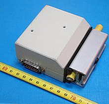
A Thicknet transciever (vampire tap) used to connect a computer to a Thicknet Ethernet network. Via Wikipedia.
Recommended viewing: Vampire Tap Demo by David Bombal
This is one of those ethernet vampire taps, which bites into the cable (here, a yellow jacketed cable is seen) and adapts to a common serial port. It reminds me of how old ranchers used to hook telephones up to their barbed wire fences. Since barbed wire is wire, it carries a phone connection almost as well as a regular phone line. And since the fence goes all the way around the property, it connects you to your neighbors. Anyone who wanted to be part of the barbed wire phone network just had to attach their fence to their neighbor's.
Wiring like that formed a party line rather than a line that you could dial numbers on. Anyone who picked up their handset was in a group call with everyone else on the line. That's the comparison to Ethernet: in the original Ethernet standard, everyone was talking on the same line. Every device both transmits and receives messages on the single cable, almost as if it was a serial cable. This was called a "collision domain" because if multiple devices tried talking at once, their transmissions would "collide" and destructively interfere with each other. To address this problem, Ethernet introduced Data Framing, and Retransmission.
Data framing breaks a communication into discrete packages that allow for continuous transmissions to be broken into chunks. If two Ethernet devices accidentally try to send a single frame of data at the same time and end up colliding, each device re-queues their frame and tries again to send it after a random length of time. The random length of time helps to avoid the collision from happening again. This retransmission is what lets everyone talk on the same wire.
In addition to providing a clear path to address collisions, data framing also allows tagging that data with a source address and destination address by announcing them at the start of each frame. These addresses, called Media Access Control addresses (MACs), are unique addresses burned into the firmware of the ethernet cards on computers in the network. Two computers on a network must never share a MAC address.
To ensure different companies don't accidentally assign the same address to two devices, IEEE manages a database called the OUI database, which gives each standards-compliant vendor their own ID that makes up the first half of every MAC issued by that vendor. These vendors must use their prefix, followed by a unique suffix that the vendor must take care to not reuse. By this method, two pieces of network interface hardware manufactured by reputable licensed companies will never intentionally have the same MAC, but unlicensed hardware from unscrupulous companies tend to reuse addresses, or make up entirely fake OUIs leading to conflicts. This doesn't happen often, but it has been known to occur when ordering discount equipment in bulk.
| Length | Description |
|---|---|
| 62 bits | Preamble used for clock synchronization |
| 2 bits | Frame Start |
| 48 bits | Destination Ethernet MAC Address |
| 48 bits | Source Ethernet MAC Address |
| 16 bits | Length or type |
| Variable | Data |
| 32 bits | Frame Check Sequence |
Here's a simple ethernet frame format. When your computer tries to talk Ethernet, it follows this format. The first 62 bits are used to help the network interface devices synchronize their clock signals so they can make sense of the upcoming message. Then there are two bits to mark the start of the message. The next 48 bits encode which MAC you're sending to, followed by another 48 bits to encode which MAC you're sending from so that the destination device can reply. Then there are 16 bits to encode the length of the message, followed by the actual message bits. Finally there is a "check sequence" which contains a check sequence to allow listeners to check whether the frame was corrupted during transmission.
Ethernet's physical components work a lot like Serial's. That 10BASE5 thicknet standard used 1 volt to signal ones, 0V to signal zeroes. All 10BASE5 devices communicated at a data synchronization rate of 10Mbit/s. However, Ethernet went through several Physical layers (PHYs) before it settled on the cables we use today. After Thicknet came 10BASE2, also called Thinnet because it used thinner cables. The 10 is because it still operated at 10MBit/s, and the 2 is because the thinner wire reduced the maximum length to about 200 meters. Thinnet was also called Cheapernet because the thinner cables were notably cheaper than Thicknet's cables.
Rather than using vampire taps, Thinnet cables used BNC connectors at every connection point. A device would join the network by twist-locking into a T-connection anywhere along the long 200 meter network cable.
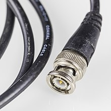
A Thinnet cable with a BNC connector. Via Wikipedia.
After Thinnet came 10BASE-T, which is the precursor what we use now. 10BASE-T, called Ethernet over Twisted Pair. 10BASE-T typically uses the 8p8c connector design (8p8c standing for 8 position 8 contact). With 8 positions/contacts, that makes 4 pairs. Each pair of wires are twisted themselves into a helix shape to help avoid external interference, with each pair in a cable getting twisted at slightly different rates to prevent them from interfering with eachother.
Signals are sent along these pairs as the difference between voltages on each wire. One side gets +2.5v, the other side gets -2.5v, and the signal is the 5v difference between the two. The two wires have to be twisted around each other so that, on average, external interference that increases or decreases the voltage on the cable will increase or decrease the level on each line about the same amount. For example, if there's +.5v of interference, the levels will be received as +3v / -2v and the signal of 5v difference will be preserved.
At the 10Mbit/s and 100Mbit/s data rates, 10BASE-T only actually utilizes two pairs (one for transmission, one for receiving). The remaining two pairs can be used to connect a second computer, or to enable a single cable to carry both the network connection and a phone connection for a desk at an office. Those extra lines also made the cable a little more future-proof.
Unlike 10BASE5 and 10BASE2's strategy of one really long cable, the separation of the transmit and receive lines required every device to have its own cable that went to a central hub. The hub would take one device's transmit line, and connect it to everyone else's receive line. Similarly, it takes everyone else's transmit line, and connects it to that original device's receive line. This turned Ethernet from a a bus topology into a so-called "star topology" where everyone communication passes through the central hub device before reaching its destination.